i)
Checking the Tx power chain Q2-Q3-Q4 for power levels
Not sure where the power
level drop might be? Try this simple test. If you have a big rig
to listen to your Phaser transmission with, you can do the following:
Connect a clip lead (leave the other end free) first to R22. Note the
signal strength. Then move the cliplead to the tab on Q3- the signal
strength should increase quite a bit. Finally, move the cliplead connection
to Q4's heat sink. That signal should be somewhat stronger than the Q3
reading. If it's the same- or weaker- Q4 may well be suspect.
“I wasn't
expecting the heat sink on Q4 to be too hot to touch after only two CQs. Is that
normal?”
a) The heatsink does
indeed get warm, as it is supposed to. Even too hot to the touch after a while,
but this is still okay. However the heatsink CAN get too hot if your Phaser is
producing distorted signals due to overdrive. That’s why we emphasize not to
crank R10 up all the way.
b) Heatsink
temperatures can get pretty hot to the touch during extended TUNE or high
duty-cycle transmissions. We’ve measured the temperature of Q4 and its heatsink
at 170-degF after a 10 minute tune cycle, which is still within the safety
window for safe device operation.
c) If you are still
worried about having such a hot heatsink, or if you operate high duty-cycle
‘conversational’ modes such as JS8 and PSK31, then it is possible to install
another heatsink (Digi-Key A10760-ND) on the backside of the existing one, or a
‘heat
spreader’ to the existing one, such as the copperclad pcb material supplied
in the Enhanced Heatsink of the 'Value Pak'.
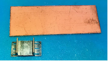
'Enhanced Heatsink' components as supplied in the Phaser 'Value Pak'.
Extra heatsink can be soldered to the back of the original one.
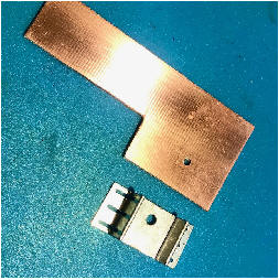
Or, cut the copperclad material as-desired, drill
a hole in both the board and the heatsink and secure together with a nut & bolt
to achieve greater heatsinking capability.
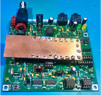
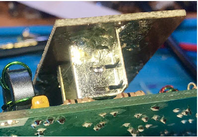
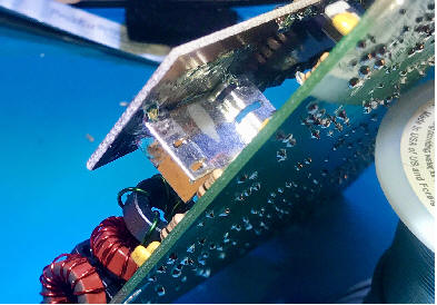
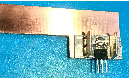
Or for even better thermal conductivity, try
soldering the copperclad board directly to the heatsink!
This example board is soldered to the top of the heatsink while it and Q4 are
still in place on the Phaser board. Just make sure you have a hot
soldering iron.
(Mine uses a medium-sized wedge for good thermal mass, and the tip can reach
460-degC.)
NOTE: The solder blobs around much of the perimeter are actually bare
wires placed through tiny holes drilled in the board and soldered to both sides,
thus connecting both side of the copper and providing even more copper surface
area for the heat to dissipate.)
If
you need to replace the PA transistor and attach a heatsink, this procedure
might work for you:
a) Use a chisel tip on the
soldering iron - it provides better heat flow than a pointed tip. If you can,
crank the temperature all the way up (e.g., 750-degF works well.)
b) Pre-tin Q4's heatsink tab
first, then apply heat to the heat sink while it's resting on a heatproof mat,
for example a fiberglass mat- the kind use by plumbers to avoid damaging wood
surfaces in close quarters.) With the iron, it takes 4-5 seconds for solder to
pool on the heat sink.
c) Use a piece of antistatic
foam to hold the PA transistor, as the transistor gets too hot to hold and it is
a static sensitive device.
d) Marry it up to the heat
sink by applying the iron to the tab on the transistor. The heat sink is still
hot and it doesn't take long before you see the solder flowing again.
e) Once the solder's
flowing, remove the heat and use a small screwdriver to press down gently on the
transistor. That holds it in place until the joint solidifies. You might be
surprised at how long that heat sink will be too hot to touch!
As
a practical matter, yes. The spurious requirement is no more than -43 dBc when
operating below 30 MHz. Good amateur practice puts the carrier suppression at
40 dB and we don't make that number. Our harmonic content is all down 50 dB or
better and there are no non-harmonic spurs. That's what matters. Short
version: The Phaser is legal.
[We should point out that DSB rigs have an unwanted and unusable sideband at
full strength... and probably a fair of amount of carrier leakage. Those are
legal, though the Phaser does far better.]
“What ‘RADIO’ does one choose in the WSJT-X
settings when using the Phaser?”
In
Settings --> Audio tab. The Radio should be set to 'none'. That's because CAT
control isn't applicable. To its right, click on 'VOX'. The Phaser switches to
transmit whenever it senses audio from the computer sound card.
In
Settings --> Audio tab. Audio settings are based on how your computer provides
access to its ‘soundcard’. Many computers provide a separate stereo ‘mic input’
and a stereo ‘headphones’ output jack that may be conveniently used for
connecting the Phaser. Others may need you to select 'Headset Microphone' for
input and 'Headphones' for the output. You may also need to select which
left/right channel is to be used for the audio, in which case you can try
selecting 'left' for the microphone input and 'both' for the headphones.
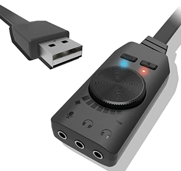
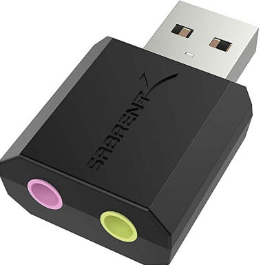
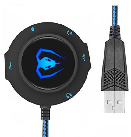
External soundcards can be a convenient and inexpensive way to use for
connecting to the Phaser. Oftentimes just plugging one of these little devices
into the USB port will trigger Windows to find and install the driver required
for it and you will be rewarded with a ‘ding’ sound when the computer is ready
to use that new device. Then just go to the Settings --> Audio tab and be sure
the Audio input and output selections indicate the USB source for the audio,
In general,
the Phaser transceiver is capable of working any ‘linear’ amateur digital mode
that transmits and receives audio tones within a 1200 Hz window in the upper
sideband. Examples include FT8, JS8, PSK31, RTTY, Feld Hell, Olivia, MFSK, SSTV
and more.
i)
JS8 is
a digital mode
that uses the robustness of FT8 combined with a messaging and network protocol
layer for weak signal communication on HF. Users are able to exchange arbitrary
length messages using multiple 15-second frames to send/receive. JS8 uses a
keyboard messaging style interface to enable hams to actually exchange normal
QSO information operating under weak signal conditions.
JS8 uses the FT8 protocol as its underlying structure, and its 15-second frame
is comprised of 13 seconds Tx and a 2-second pause to receive an ACK from the
other station. Then the JS8 protocol continues onward with transmitting its
next bock of data in the next frame.
(Note: This higher duty cycle mode of operation causes the Phaser’s final
transistor to get warmer than when using most any other mode.)
ii) The Phasers will
work with both modes FT8 and JS8 ‘out of the box’. The Phaser powers up with
the green LED ‘on’ indicating the frequency is set to the FT8 window; and the
user merely needs to tap the pushbutton beneath the yellow LED to switch to the
ALT (Alternate) frequency, which is preset for the JS8 window in each band.
While there are many FT8 users in the bands, as I’m sure you’ve seen with your
WSJT-X app, there are not too many JS8 users … perhaps just too new or perhaps
people tire of waiting for the full messages to come across. It’s not like the
‘conversational typing’ mode of PSK31, but JS* (and FT8) are most assuredly
terrific for weak signal 2-way communications.
You
can work RTTY stations with the Phaser. It's a little more work but totally
do-able. One way is to use FLDIGI - the 'Swiss Army knife' of Amateur Radio.
Move the ALT frequency a few kHz at a time and calling the stronger signals that
you can copy. Because the Phaser receives both sidebands, half the signals
won't decode. [You can swap the Mark/Space convention in FLDIGI to copy them,
but you won't make contact.]
"The WSPR frequency is 7,038.6 kHz, but I can
only program the Phaser’s ALT frequency with 1 kHz resolution."
i)
The Phaser’s
ALT frequency can be set to the WSPR frequency of 7,038.6 kHz, despite the
lowest resolution being 1 kHz. Just calibrate the Phaser to be 400 Hz lower
than the reference used – then when program the ALT frequency to 7039 kHz then
you will actually be right on 7038.6 kHz. And when it comes time to run FT8 mode
again, tapping the FT8 frequency button will put the frequency 400 Hz lower than
usual for that mode, but you can then just use the upper end of the FT8 window
in WSJT-X.
ii)
Another
approach is to use the WSPR app (WSPR2.0) rather than WSJT-x. You can set the
dial frequency to 7038 and set the audio offset (under the advanced tab) to
2100Hz and the Phaser will work perfectly. Use a little math to set the TX
frequency in the software where you want it, but this is lots easier than
re-calibrating the Phaser.
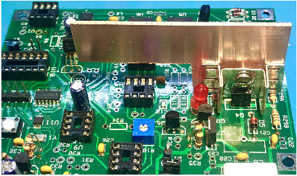
“How can I determine when my Phaser is transmitting?”
A
simple addition to your Phaser can serve as a Tx mode indicator. Just place a
red LED and 3.3K resistor in series from the top of L3 (the 12V switched bus Vsw
for the transmit strip) to a ground conveniently at the top of nearby R26. Then
whenever your Phaser is commanded by WSJT-X to go into transmit, the red LED
will come on. You might consider adding the LED to a new hole in the front panel
right next to the arrow in the Phaser logo and your Phaser will look STUNning!
[Note: We have added this LED-and-resistor to the Rev C pc board that started
shipping in Round 4 kits.]
It's a transmitter and it's designed to radiate! <g> The imperative for
shielding came in the TVI days and that's no longer a real concern. The other
reason for shielding was due to 'hand-capacity' effects, and that too has been
eliminated with the digitally-controlled oscillators.
The voltage at R34 actually stays very low (~0.5V) then suddenly flips up to
about 4.5V when the WSJT-X ‘Pwr’ slider reaches a high level.
This operation with the 4V test is normal. Once the slider reaches the Phaser's
threshold, the 4V bias will come on suddenly to switch the Phaser to Transmit.
It is OK if that happens at almost full-scale on the slider, but that might
indicate that you don’t have enough audio from your computer sound card.
Yes, you may see signals decoding with just a dummy load on the Phaser’s antenna
port. There's gain to spare with the Phaser receiver and the computer sound
card. I've gotten decodes with a dummy load connected to J1, and several other
folks have noted the same thing. The traces going from J1 to U13 (the receiver
mixer) are fairly long, and that's where the signal pickup is occurring.
A
technique I use when replacing TO92-packaged parts like U7 and U8 is to just
carefully snip off their leads close to the pc board. I usually do not try to
unsolder the parts because I worry about messing up the pads by applying too
much heat, lifting the pads off the board, etc. So when it comes time to add the
new part …
a) I first
clip the new part’s leads kind of short.
b) Then I
place a nice solder blob on each of the pads.
c) And finally, I hold the part in the right
position with one hand, nice and perpendicular to the board and next to one of
those solder blobs, and then lightly solder one lead in position. I
double-check that the part is upright, in the right orientation, and positioned
with the other two leads (still unsoldered) next to their respective pads with
the blobs. When everything is good, I carefully solder the middle lead to its
blob, and then the last lead to its blob.
We
considered 12V as the nominal supply voltage for the instructions. In reality
it's more like from 10V (resulting in considerably reduced power output) to a
maximum of 15V. The low end is perhaps as little as 7V, but there'll be
miniscule output power if you use this supply voltage. At the high end, a 15V
supply would be OK. If we had to recommend a range of supply voltages, it'd be
10-14V DC, with the understanding that it will work somewhat beyond that range.
You can absolutely go to 13.5V or a little higher. 13.8V comes to mind as a
standard transceiver supply voltage, and there's no harm in using that if you
have it.
If
your computer has a single 4-pin jack instead of separate ‘mic in’ and
speaker/headset jacks, there’s a solution. There are several Y-adapters
available:
a) Tripp Lite P318-06N-FMM (Digikey # TL1631-ND)
b) StarTech.com DH ‘ST 3.5mm Headset Splitter’.
This one was available at a local computer service emporium.
Either of these also requires a 4-pin male-to-male
cable between the computer and the Y-adapter:
c) Tensility 10-02153 (Digikey # 839-1407-ND).
This one is 3 feet (0.9m) in length. Other lengths are available.
d)
Ray AE5HN tells us that he was using a laptop with the 4-wire audio connector (TRRS),
not separate headphone/mic and wasn't getting the proper response. When he
realized that, he ordered an adapter from Amazon like
this one to solve the problem.
"PSKReporter shows my frequency as 7.0754 MHz. Should I recalibrate?"
The
PSKReporter frequency indicates the actual signal, which is the AFSK shift from
the base of the FT8 window up into the upper sideband. Look for the number
listed next to your outgoing transmissions in WSJTX (e.g., 1400 Hz in your case)
and add that to your nominal tuned frequency of 7.074 MHz and that should
roughly match the PSK Reporter figure you see.
Another couple of ways to
Calibrate ...
Set your frequency in
WSJT-X to 1,000 Hz and you should hear a 1 kHz tone on the big rig when set
to 14.074 USB. And if you 'zero beat' that tone my moving your big rig
dial 'up', it'll end up being close the actual frequency of 14.074 +1 kHz =
14.075.
Or ... set the big rig
dial to exactly 7075 kHz and the WSJT-X frequency to 1,000 Hz, and use the
S1 or S2 pushbutton in the Phaser's Calibrate mode to zero beat the tone.
L-3, the coloring on the component is brown, green, gold and silver. Not brown,
green, gold and gold as described in the most recent assembly manual. The
‘silver’ band on the end is component tolerance of 10%, vs a ‘gold’ tolerance of
5%. Either is good for our use.
17.
What is the audio
bandwidth?
“I’ve
run a copy of JTDX set to FT4 and successfully decoded FT8 (3.573) on WSJT and
FT4 (3.575 Mhz) on JTDX at the same time. Opening up the waterfall it suggests
the audio bandwidth is at least 5.5 kHz. Is this correct??
Yes- that's correct. The -3dB audio response on the receiver is on the order of
5.5 to 6 kHz.
"Running FT8 (3.573) on WSJT and
FT4 (3.575 Mhz) on JTDX at the same time, looking at one water fall, is it
possible to Transmit across the whole FT8/FT4 bandwidth (3.573-3.578 Mhz)?"
I'd
recommend against straying very far from the phasing circuitry's 'sweet spot' of
800 to 2800 Hz.. Unwanted sideband content comes up pretty quickly below 800
Hz. Above 2800 Hz, the unwanted sideband comes up more slowly. If I
recall, it's still down 30 dB at 3600 Hz, but I didn't carry the measurements
any further. You've always got the option of reprogramming the ALT frequency a
couple kHz higher for JT4 operation.
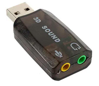
Some
examples … TechRise USB External Stereo Sound Adapter Splitter Converter with
Volume Control for Windows and Mac,Plug & Play No Drivers Needed ... <https://www.amazon.com/gp/product/B01J7P0OGI>
As
of the moment, a 10M PCB prototype on the bench is putting out 3Watts. The
carrier is down 35 dB and the unwanted sideband is down 30 dB, as measured on a
spectrum analyzer. Two significant changes from the existing Phasers are
required. First- there's not enough Transmit strip gain. I've added 12 dB of
additional gain using an inexpensive MMIC device. The other change eliminates
the FST3257 devices (U5 and U6) and replaces them with ADE-1ASK mixers. George
and I have not yet discussed plans for how and when this would hit the streets,
and I'll ask folks for patience on this. We've got plenty else going on right
now.
Thanks for asking! Yes- there's always that chance. I'm simply not there yet.
Once we have the 10 Meter version under our belts, there are several more
functional changes needed for 6M. The Si5351 won't clock at 200 MHz, so
generating 50 MHz quadrature RF has to change. This'll take the form of some
added low-pass filtering and a quadrature (Fisher) hybrid. It remains to be
seen how much output power the Tx will develop. The FCC requirements for
spectral purity are also more stringent above 30 MHz- -54dBc instead of the
-43dBc for HF. That means additional low-pass filtering or a different approach
for the PA…To be continued ...
“I like to
measure the inductance before I install it. The inductance values do not appear
in the schematic, parts list, nor PC board.
“
a) There's an easy way to
come up with the inductance values: Go to
kitsandparts.com, select the toroid type, and it'll open a dialog box. You
enter the number of turns and it'll spit out the inductance.
b) What you measure will
generally not match those results- for several reasons. The winding integrity
will affect the inductance. The biggest variable is the turns spacing.
Inter-winding capacitance increases the effective inductance, so it pays to
space the turns as evenly as possible. The inductance calculations don't take
this into account, as far as I know. There's also some amount of lot-to-lot
variation in the core characteristics. The Phaser does use toroids from
KitsAndParts.com and Diz buys in large quantity. As such, the AL value will be
pretty consistent from unit-to-unit
C) The other factor that may
affect the measurement integrity is the measuring instrument itself. A meter
that does a great job in the millihenry range may be less accurate in the
1-microhenry ballpark. A decent way to test this would be to use a 1uH 5% RF
choke with short leads. You've probably checked this already and are confident
the measurements are good.
d) All of which begs the
question: What do you do with the results? They'll typically read higher than
the calculated values. At some point, the measurements will differ from the
calculations by enough to be meaningful. For the sake of discussion, a
measurement 20% higher than the calculated value starts to become meaningful- IF
you trust the instrument itself. The low-pass filter (L4 and L5 and related
capacitors) will begin to roll off output power at the design frequency. The
effect is like having an excess turn on one of those two inductors. If that's
the case, it won't hurt to remove a single turn from the winding.
e) L3 isn't especially
critical- it's part of an L-network that's based on a presumed 20-ohm impedance
looking into the PA. L6 is non-critical- its impedance is on the order of
several hundred ohms (IIRC). That's high enough that it doesn't materially
affect the calculations for the collector impedance and low-pass filter.
24. Turn
count for L6 in Phaser-40 ... 16 or 17 turns?
L6 should have 17 turns, jut like in the previous
version of the pcb. (The version C1 document has been corrected
- sorry about that!)
25. How to install 'D8', the red Tx Indicator LED into the Enclosure front
panel
The red Tx Indicator LED
(D8) may be simply installed in the enclosure by drilling a 7/32” hole near
the ‘arrow’ on the front panel (or anywhere else you might wish) and the
sticking the LED in it. Any kind of glue/epoxy/hot-wax will work to hold it
in place. Then solder two wires from the LED to the spot in the pcb it
would otherwise go. The Enclosure Kits were designed and produced long
before the idea of having a Tx indicator, so it’s up to the builder to
‘homebrew’ it in place, if desired. Otherwise just solder it in place on
the pcb and things will still be fine … but you won’t see the Phaser go into
Tx mode when in the enclosure.
26. No 'FT8' or 'Alt'
labels on front panel
Most of the kits now do not
have FT8 and ALT noted on the outside of the enclosure front panel. There
was a problem at the fab house on the labeling, but we decided that it
wasn’t too much of a concern, as the operating mode is fairly obvious by the
colored LEDs and their associated switches. One could place any label
desired on the panel under these switches – say FT8 and PSK31 – just as
their operating habits might uniquely be for their unit. Again, stay tuned
on this one too and we’ll have some labels that user can download and apply
if they wish.
27.
I need to use a longer-barrel plug for the Phaser power
Yes, the plastic molding
around the shorter plugs prevent full insertion through the enclosure’s rear
panel. For years I have standardized on using the longer power plugs in my
kits (Mouser p/n: 490-PP3-002A) and we selected the hole in the rear panel
accordingly. If you do have a shorter plug, you can easily make the hole
bigger using a file before inserting the Phaser PCB. (We’ll make the hole
larger in future orders from the pcb fab house.)
28.
Board doesn't lay flat on the bottom of the enclosure
When the
BNC nut is tightened to the Enclosure rear panel, the board will ‘tip up’ a
little and the two nylon standoffs will be in the air about 1/4-inch at the
front edge, which is just fine. The board is secure in this position.
29.
Power supply recommendations for the Phaser
Those using their Phasers
in the field use the portable 12v battery to provide the juice. And
for the bench in the shack, most just power the Phaser from the existing
(beefy) 12V power supply used for powering the 'big rig'. But those
who don't have a bench supply might try a good “AC adapter” that provides at
least 12V at 2A. Something like this at
DXEngineering.com or
MFJ.com should work fine. Alternatively, you could try the
Pyramid
PS3KX.
30.
Test #2 Problem -- “The LED doesn’t turn on during TUNE”
Apply the 12V power but do not connect the audio
cable. Then temporarily ground pin3 of U9 by briefly touching the pin with
a wire which is connected to ground. That should cause:
1) U9 pin1 to toggle low [CHECK
FOR IT]
2) and U9 pin7 to toggle high [CHECK
FOR IT]
3) and the junction of R35 and R36 to toggle to
about 1V [CHECK FOR IT]
4) and Q7 to toggle on, which supplies 12V to
L3 the red LED to light. [CHECK FOR IT]
If things all work as described above …
5) connect the audio output from your computer
to J3 and click on TUNE in the WSJT-X app.
6) Briefly run the ‘Pwr’ power slider up to
maximum. Red LED turn on? [CHECK FOR IT]
6a) If no, the audio level from your
computer either isn’t coming out or is simply too low.
6b) Plug earphones into the computer audio
jack … Do you hear the tone when you click on TUNE? [CHECK
FOR IT]
6c) If you hear a tone it may not be loud
enough … Go to your computer Sound Settings and make sure the master volume
is set to 100%. [CHECK FOR IT]
31. Power output dips during long transmissions
The PA transistor (Q4) is likely overheating
whereby its internal resistance decreases and it draws more current- a
positive feedback effect. The current limit function of Q8 is thus likely
being triggered which causes a corresponding lowering of the voltage on the
Vsw bus. If you monitor Vsw when the power dips, that will confirm it.
This ‘current limiting’ circuit is described in the Phaser Knowledge Base.
The PA can get ‘too hot’ due to long
transmissions and/or when the load (i.e., the antenna) has a high SWR.
Always use an antenna that is resonant at the Phaser’s frequency, and if
you engage in extraordinarily-long transmissions, you can try adding
additional heatsinking to Q4 – see the Phaser Knowledge Base item #2 for
examples and photos.
Current Limit Operation:
Starting with revision C Phasers, the Transmit bias switching was
significantly upgraded. The bias switch- a 2A-maximum PNP transistor- was
replaced with a 16A-max P-channel MOSFET (Q8). Additionally- a new
transistor (Q8) and ‘sense’ resistors (R47-A and -B) were added. Under
normal Transmit conditions, the voltage drop across the sense resistor is
not sufficient to cause Q8 to conduct. At about 0.7V (0.8 amps), though, Q8
begins conducting. When it does, it pulls the Gate bias on the MOSFET
toward the positive supply. This is in the direction of turning off the
MOSFET. It’s actually an example of ‘negative feedback’, and it sets a
stable current-limit of about (0.7V/0.9 ohms) or 800 mA.
Why? The PA device (Q4) is
rated up to 5 Amps max current. It was possible to approach this value when
turning R10 fully clockwise for maximum drive. We replaced a number of PA
device after their heatsinks fell off, or Q7’s ratings were exceeded. Q7
typically registered its protest by emitting smoke. The 800 mA current-limit
function introduced by this change should be ‘transparent’ to normal
Transmit operation.
32.
Phaser is deaf -- I don't see any band activity on WSJT-X screen
Here are some things to check ...
1) Are you using 3-wire stereo audio cables for
audio to/from the computer?
2) Is your computer sound system set to 100% in
the mic input? (See Aduio Settings elsewhere in this KB document, as
it applies equally for the incoming audio path.)
3) If you plug your earbuds into the Phaser jack
J4 (outermost one) are you able to hear the FT8 signals when the antenna is
connected? (It will be low but you should clearly hear the digital
activity.)
4) Did you hear the Phaser’s local oscillator in
your big rig during Test 3 (on page 12 in the Instructions)?
5) Are you certain that you stripped back the
enamel wire when preparing/attaching L5 and L6? (You can easily check this
– should have continuity between the BNC center conductor and the left side
of C1 down in the lower-left corner of the board.)
33. Is there another audio
source that could be used if WSJT-X is problematic?
Here is a PC soundcard
application with a signal generator, scope and spectrum analyzer that I have
used for years ...
https://www.zeitnitz.eu/scope_en
The FT8 TUNE function outputs a sign wave from less than 500 Hz to more than
2400 Hz depending on SHIFT+RIGHT CLICK mouse pointer... then the RED TX
icon points to selected frequency. Caution: This application
has the potential to launch VOX into the next solar system !!!
Remember that an alternate audio source of 0.2 V at 1 kHz is plenty, as
measured with a multimeter set to an AC voltage scale.
Back to Phaser home
page
Contact Us
Discussion List: Chat With The
Designers ...
https://groups.io/g/cwtd/topics
Questions?
Email to George N2APB ...


Copyright 2019 Midnight Design
Solutions, LLC. All Rights Reserved.
Page last updated: June 30, 2020